Introduction
Creating a location system on the moon presents an interesting challenge. Unlike on Earth, there are no GPS satellites with which to calculate position. A location system that works on the moon will need to be created ad hoc. The location scheme takes advantage of the relatively unobstructed surface of the moon. By using small RFID breadcrumbs dropped by the astronaut, the astronaut can know his/her location at all times while on his/her lunar journey.
Position Estimation Scheme
Distance Estimation
To determine the astronauts distance from a particular breadcrumb, a signal strength reading will be compared to a baseline signal strength reading. Consider the basic link budget equation:
Eqn 1. Link Budget Equation
Angular Estimation
To determine the astronauts angle from a given breadcrumb, three antennas will be placed on the astronauts backpack in a triangular arrangement as shown in Figure 1.
Figure 1. Antenna Orientation on the astronaut.
Using these three antennas, an angle estimation can be made using a time difference of arrival scheme. If all antennas are receiving the same signal, each will receive the signal at a slightly different phase.
A two-dimensional position can be achieved utilizing three receive antennas and one transmitter by utilizing the Time Distance of Arrival (TDOA) determined by the geometry of the three antennas and the location of the astronaut. The antennas receive the signal and a multilateration technique is utilized to determine the angle from which this signal is received. Multilateration, or hyperbolic positioning, involves the computation of the TDOA. The TDOA is then used to determine the position of an emitter by looking at the intersection of two hyperboloids.
Two equations and two unknowns are determined through the geometry of the antenna pattern as seen in the following equations.
τB = TB TA = c-1 * (sqrt[(x-xB)2 +(y-yB)2] sqrt[x2+y2])
τC = TC TA = c-1 * (sqrt[(x-xC)2 +(y-yC)2] sqrt[x2+y2])
The angular position of the astronaut can be determined to reinforce the signal strength location algorithm. More antennas could be utilized to either provide more accuracy or provide three-dimensional accuracy.Four Antenna Procedure
One method for lunar location is to use 4 antennas. One antenna is dedicated to communication back to the lander. It will not be used for determining location. The other three antennas are used for distance and angle estimation from a breadcrumb. The location procedure is as follows:
1. Upon leaving the lander, drop a breadcrumb. Record the baseline signal strength, breadcrumb GUID, and an x-y coordinate of (0, 0).
2. Walk until the astronaut is either about to move out of line of sight (LOS) of the breadcrumb or the signal strength from the breadcrumb is about to reach a threshold value of -82 dBm (The reader can function at a signal strength of -85 dBm).
3. Drop a breadcrumb. Record the baseline signal strength, breadcrumb GUID, and x-y coordinate. The x-y coordinate is determined by using the distance and angle estimation from the previous breadcrumb.
4. Continue walking until the astronaut is either about to move out of LOS of the last breadcrumb or the signal strength from the last breadcrumb is about to reach a threshold value of -82 dBm.
5. Drop a breadcrumb. Record the baseline signal strength, breadcrumb GUID, and x-y coordinate. To determine the x-y coordinate, first perform a distance and angle estimation from the previous breadcrumb as a rough estimate. Then, read the signal strengths received from other nearby breadcrumbs. If the received signal strength from the other breadcrumbs is within .5 dB of the expected signal strength based on LOS conditions, then we assume that breadcrumb is within LOS. Perform a distance and angle estimation from this breadcrumb to improve the x-y coordinate estimation.
6. Repeat steps 4 and 5.
By dropping breadcrumbs before moving out of LOS of the last breadcrumb, the scheme ensures at least one LOS distance and angle estimation. It is important to only consider LOS distance and angle estimations when determining a breadcrumbs x-y position because non-LOS measurements will be inaccurate.Six Antenna Procedure
The 6 antenna scheme is very similar to the 4 antenna scheme. The main difference is that the signal from the lander is also used for location estimation. Three antennas are used for breadcrumb location estimation and three antennas are used for lander communication as well as location estimation from the lander. The location procedure is as follows:
1. Record the baseline signal strength from the lander and an x-y coordinate of (0, 0).
2. Walk until the astronaut is either about to move out of line of sight (LOS) of the lander or the signal strength from the lander is about to reach a threshold value of -49 dB.
3. Drop a breadcrumb. Record the baseline signal strength, breadcrumb GUID, and x-y coordinate. The x-y coordinate is determined by using the distance and angle estimation from the lander.
4. Continue walking until the astronaut is either about to move out of LOS of the last breadcrumb or the signal strength from the last breadcrumb is about to reach a threshold value of -82 dB.
5. Drop a breadcrumb. Record the baseline signal strength, breadcrumb GUID, and x-y coordinate. To determine the x-y coordinate, first perform a distance and angle estimation from the previous breadcrumb as a rough estimate. Then, read the signal strengths received from other nearby breadcrumbs as well as the lander. If the received signal strength from the other breadcrumbs or lander is within .5 dB of the expected signal strength based on LOS conditions, then we assume that breadcrumb or lander is within LOS. Perform a distance and angle estimation from the breadcrumb or lander to improve the x-y coordinate estimation.
6. Repeat steps 4 and 5.
Accuracy Analysis
Several types of standard deviations can be utilized to present problems for a location system. The clocking of the microcontroller, receiver noise, and multipath effects can present a significant roadblock to the precision of this location system. The noise received at the receiver can provide up to a 1.13 m of precision errors with a 3 dB degradation in the signal strength. The upgraded clocking of the microcontroller can provide up to 3 m of precision errors when determining the angle of arrival from the current signal. Multipath effects contribute about 3.0 m of errors as well.
The RMS error results in approximately 4.39 m of accuracy. The astronaut will be within 8.78 m of his estimated position 95% of the time.
The cons of this system require that there are LOS conditions which we account for in the procedures that have been set forth. Another con is that the microcontroller requires an upgraded clock to minimize errors in determining when the signal is received at each antenna. A combination of the received signal strength and the angle of arrival calculations provide for a better dilution of precision for the astronaut. The signal strength range measurement gives a moderate standard deviation and gives satisfactory readings for the astronaut to be able to return to the lander safely.
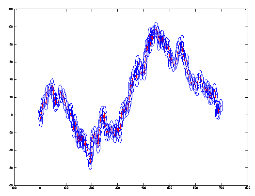
Figure 2. Random Eastward Lunar Walk.
Possible Improvements
Some tweaks can be made to the location algorithm to improve accuracy and power usage. The first adjustment pertains to the astronauts return journey back to the lander. Breadcrumb location estimations become less accurate as they get farther away from the origin (lander). Therefore, as the astronaut returns back to the origin, only breadcrumbs that are closer to the origin than the astronaut should be considered in location estimation.
Another adjustment that can be made to reduce energy usage is to use a variable transmit power to excite the RFID tags. As the astronaut is walking around, the main concern is that the astronaut not move a certain threshold signal strength value away from the last breadcrumb. For determining when to drop the next breadcrumb, a lower transmit power can be used. When the astronaut drops a breadcrumb, a higher transmit power should be used to excite more possible breadcrumbs.
The Matlab Algorithm